
Topological cleaning
This is called the action of the GIS tools to eliminate vector inconsistencies to the norms commonly accepted in the Spatial topology. Each tool has implemented them in its own way, let's see the case of Bentley Map and Manifold GIS.
Microstation Geographics
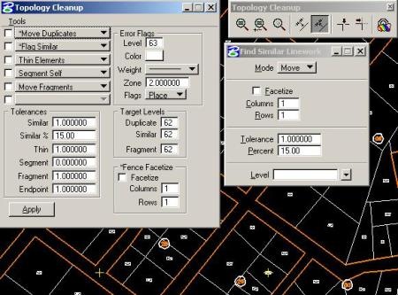
Microstation includes two tools for the same, one activated by keyin (dialog cleanup) and the other known as topology Cleanup. For reasons of dispersion, we all prefer the first one, although there is no other button for this than the old-fashioned command.
It includes six topological options in the left frame, while in the lower part are the tolerances and to the right the destination and characteristics where the indicative of inconsistency is expected. Although it is called topological cleaning, it is not the most appropriate name, rather they are vector cleaning tools among which it includes:
- Duplicate elements
- Related Items
- Thin, little was used but it is to determine the abuse of vertices unnecessarily
- Segmentation.
- Fragments.
- Loose elements
For almost each one there was the alternative of choosing the destination of the error, option to mark it or eliminate it and tolerances. It wasn't bad, there were even the mrf tools compiled with mdl that let you browse the bugs. But it used to be a headache in any case, not because of the cleanliness that was sharp but with the later utility in spatial or topological analysis. To give an example, in different map layers, the non-coincidence of nodes was a problem, crazy.
Bentley Map
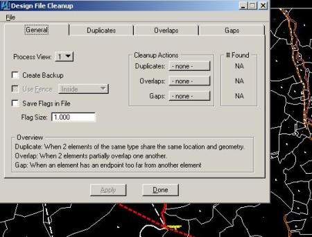
The penel changed with Bentley Map, there is always the Dialog Cleanup Although it requires having a project open, but the other alternative was concentrated on a single tabbed panel. Additionally, very functional options were added:
- View filter control
- You can filter the type of objects (line, arc, polyline etc)
- The match can include line type, color or thickness
- Create automatic file backup
- Overlap can bypass duplicates
- The configuration can be saved as a .rsc file and recalled
- Thin was removed, that nobody used because it did not work
It would be necessary to test if the headache is improved with the topological analysis, since it was too rigorous and demanded accuracy of too crazy splices so that the tolerances did not make sense. Alert flags are also non-dynamic vector objects, which makes much of the work a visual skill rather than a dynamically sized cell.
Manifold GIS

Bentley must work hard on the subject, because although Bentley Map Supports topologies, it is half taken from the hair. Additionally it does not support easily complex geometries, which perhaps do not occur much in the cadastre but in other layers such as vegetation cover or risk areas, to put a couple of examples. In Geographics it turned them into Cells or complex shapes, So that you could not Do topological analysis. It should simplify the process, because most programs have made great strides in this, for example, using the Scullion Manifold GIS does an exceptional job without getting too complicated. This works with Tools / topology factory, Just select the objects and lift a panel that includes an immediate analysis according to the precisions of the layer:
- Closeness
- Overlapping
- Overshooting
- Contiguous branches
- Reduntant metrics
Besides, by selecting them they are shown in a different color and there is the option of individual or massive self-repair. Make tolerance change, also this is within a view with options to scroll, go next, take action and zoom.
Finally the user adapts to suffer or mix tools, but should not be accepted practice for a service that we pay and hope to improve over time.


Clarifying by doubts that have arrived at my mail.
The example shown is with Microstation Geographics 8.5
With Bentley Map V8i the handling of complex geometries such as holes within shapes is no longer a problem.
Additionally, from the management of XFM attributes with Bentley Map, the node-boundary binding logic has lost priority to do it via shape. Although the tools for making links are similar as well as those for transferring data between the centroid and the shape / boundary.
Hello; You know I wanted to know if you can help me with my problem what happens is that I want to create a new template and leave you certain predefined parameters which will help me when creating a new drawing as for example style examples of profiles, then I wanted to know how you can create A new template and this new leave you predefined new parameters of either design or styles of objects, I hope you can help me but for the other answers I realize that you are very kind in these issues so again thanks
Let's see.
To export occupies Microstation Geographics.
You must also be connected to a project, so that you export the layers with the daots.
Also, to export shapes features occupations, with associated data. It will not work for nodes and boundaries.
If all is well, tell me if sending the export sends you a message. You can also try opening the dbf file with Excel to see if it has data.
Hello this topic is excellent, I would be very interested to know if, because it is not possible to export a complete file to shp since when the export ends, it generates the incomplete data of this I realize when I try to import the file again through the bentley map
Would infinitely appreciate if anyone has any solution or advice
thanks!
okay! Let me explore for a while autocad map, and then consult them. Thank you.
Just for that is AutoCAD Map 3D or AutoDesk Civil 3D. With this you can do what you would do with any GIS, connect to data from a table, do topological analysis, thematic maps, etc.
If you want to put a simple hyperlink, when you open the properties of the object, you will see that there is a field called a hyperlink, where you can associate a url path of a website, a path of a file on the local disk, or a layout of Another dwg map.
In the case of AutoCAD, it only supports one hyperlink per object.
Question for the experts in the subject, I have a survey made with GPS, I have it in autocad, there is some application in which I can add attributes to a CAD element or I need to create them as blocks, besides how I can link an image to the CAD element or Block, ç.
Thanks to all who contribute in this forum.
Ah ok, it seems that only 248 points were permissible, but with 996 rows it is feasible what I need to work on.
very thankful,,
Negative, the macro author protected it with password, and left it limited to 996 rows. It did this to protect the operations that are from the 996 columns, in order for the programming to work with those cells specifically.
To edit it would involve breaking the coconut with the code.
Good Excel worksheet excel, question according to the tests I've done is limited the amount of points to graph, in my case I need to perform graphs near 4000 points, how can I do to modify this excel table dynamics since I It would take too long to be plotting in sections.
grateful
Of course, the best I know is XYZ-DXF, which happens to dxf the points of an Excel listing. The Code column can contain another type of data, and the layer column allows the points to go to a specific level.
Here is Explained step by step.
Thank you very much, it works. Another question will be some application that allows me to graph DGN or DWG data stored in an Excel format, XY coordinates and that allows me to add a text legend stored in an excel field to the plotted point.
Thank you,,,,,,,,,,,
Another alternative is to use the smart selection command, with which you can make a selection by shape, and having already selected objects apply the drop.
With Microstation XM or higher, you can store the fence.
Yes,
First you make your fence
Then using the key in
Enter, fence, then choose drop, then the options appear:
-association
-complex
-dimension
-line
Choose any, and then the panel that lets you choose the type of fence condition (inside, clip, etc)
Then click on the screen and go.
question is there any application for microstation that allows me to use the command Drop Element in fenced mode.
thanks……..
Thanks friend, I'll follow your advice.
Let's see, I'll explain a couple of things.
To begin with, these versions of Geographics, (now Bentley Map) consider that a complex object is of irregular topology, meaning that a complexchain that has arcs and lines is not topologically clean.
At the bottom, the criterion that the curves are linestrings makes sense, because for the GIS programs it is complex to handle a curve at the database level, because it is a polygon of infinite vertices, so the option to pass it to a Linestring that resembles a curve is logical. Imagine how you would do to make an application that generates the box of bearings and distances, whether it was a curve or a linestring of very close points is crazy.
So in topological cleaning, when you apply segment elements, you will convert them into line srings. What you can define is the tolerance so that neither are so many vertices nor so few that the shape of the curve is lost.
This tolerance is changed in:
Workspace> preferences> topology> Stroke Tolerance.
Test 10, 1, 0.5, 0.1 and so on until you are satisfied with the segment size that the curves are left on.
Work with linear elements in which are included arcs, but when using the topology cleaning and creation of complex elements in Geographics the elements arcs represents them as lines taking the start and end point of the curve, there is way or additional tool to generate A line following the shape of the curve.
Thank you from the Savior .........
Hehe very good option, thanks for everything.
Look, there must be a more sophisticated way through templates, but I use drag-and-drop style design:
For this, what you do is open both drawings, one that has the style saved and the other that does not have it. Then you make the size of the windows smaller than the full view, so you can see them both.
You touch the window that has the style, you go to settings, surface, and there you look for the style that you want to transfer to the other drawing. Then you drag it and release it in the other window, and that's it. Now if you see the styles available in your new drawing, you're already dragged.
HELLO, again me again and let me tell you that your help did help me a lot, but, mmm ...
Now what I can not do is save the created style. I create a point style, apply it and the whole roll, but I can not make it save, that is to say that wanting to make a new drawing but wanting to use the style you create, because it simply does not appear and I have to recreate it.
If there is a way to save it and in a later drawing you can use it?
hehe ... and sorry for the inconvenience, but I know I'm a stone.
GREETINGS.
Ok, what you do is this:
In the left frame, three tabs appear:
A prospector call
Other settings
In this, the different objects that have the map, surfaces, points, profiles, pipes, cross sections etc. appear.
Then in each of them, clicking on the plus sign, the styles (surface styles) are displayed to use an example.
To create a new one, you right-click on the “surface styles” folder and choose “new”. There you can give the necessary configurations, give it a name, and whatever you want. Also from here you can modify it.
When you are working on a surface, from the prospector tab, right click on the surface, choose “properties” and in the “information” option you can choose the “surface style” that you created.
I hope the explanation is useful, anything, is not a nuisance.
HELLO, again to annoy but honestly I am a rock and I really do not know how to do it, but I still do not know if I have the availability to help me, since I'm not really up to date.
THANK YOU.
Of course, when you apply a style it gives you the option of Create a new one And save it for later use
HELLO, first a great congratulation for this site that truly is great.
And sorry for taking this space, but take a subject matter for this message to be seen. My doubt is with Civil 3D, and I want to know if it is possible to save the styles created by me (surface, contour lines, profiles, sections, etc. .).
Since once I wanted to customize these styles and my surprise was that time after wanting to use them again, because they were not saved or anything. Think they could be saved as a template. Maybe I did not do well because I get messages that I do not understand.
So I ask for help to solve this problem, please.
Greetings.