
Building the mesh of a UTM zone with Excel and AutoCAD.
Call as you want, index maps or cartographic quadrants, geodesic grid, when the name is needed it does not matter. Working this in a GIS program should be simple, but suppose what we have is AutoCAD.
A few days ago I explained the origin of the cartographic grid, and the meaning of the UTM coordinates; we will use the same 16 zone as an example, although it applies to the others, the central axis of that strip is the only line that is totally vertical and precisely it is in the east = 300,000 coordinate.

This strip has 6 degrees, and if we see it is expanding from the north pole towards the equator, where the latitude is zero; then towards the south pole it decreases, and the latitudes are the same but in the opposite hemisphere. Well how to build it
1. Let's build the coordinates with Excel
For this, simply use the tool that we had previously used to convert geographic coordinates to UTM, I will select the spheroid WGS84, then I place the latitudes and longitudes of interest:
The latitudes: From the equator to the north, each of the sections of the magnet has 8 degrees to the letter w, only x has 12 degrees, so that from N to W we would have 9 × 8 = 72, adding 12 we get at 84 degrees, in the northern hemisphere. To make it with respect to the southern hemisphere it would be exactly the same, but instead of N it would take S. GoogleEarth does not show the rest to avoid the problem that this segment would require an infinite calculation. In this case we are going to build it up to segment W.
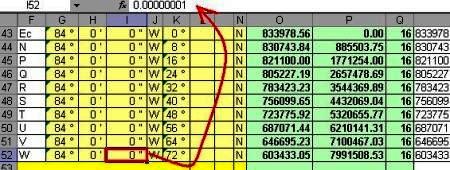
When building it in Excel we have the following table:

The lengths. If we look closely, to build the left line it only requires the limit length between zones 15 and 16 (90 degrees). To construct the right limit, the table generates a problem for me because when entering longitude 84, it calculates the same coordinates but in zone 17, so I will use 84 degrees, zero minutes and 0.00000001 seconds, so the value always falls in the zone 16 and since the coordinate is two decimal places there is no data loss.
 2. Draw the points with AutoCAD
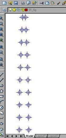
To draw it in AutoCAD, it's simple, column R has the concatenation to do Copypaste. So the content of this column is copied in Excel, then in AutoCAD, we activate the point command (draw / point / multiple point) and make paste on the command line. We immediately have the points of this mesh drawn.
If you do not see them, change the format in format / point style and leave an 5% relative to the screen.
The next step could be to draw the lines that join this mesh, but let's try to do it combining Excel and AutoCAD, because if the mesh was more dense we would have many segments of points to do.
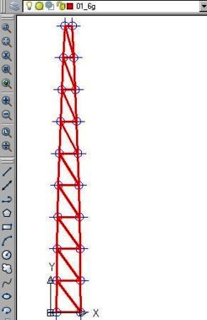
3. Construct the vertical lines.
 For this you do the same thing as to build the points, only that instead of using the point command we use the command line; and ready, just delete the leftover line.
Sure that can be done only by drawing, but remember that this mesh is only the segments of 8 degrees, when you do denser meshes you will find the utility.
4. Construct horizontal lines.
 To make the horizontal lines you only need to place the coordinates of the left limit in a column and to the right of this the coordinates of the right limit. You do this better in another column with copy and paste special, paste values, so you do not have problems with copying formulas, it should look like the image shown.
 The next thing is to select the content of both columns, then in AutoCAD you have to copy, in AutoCAD you do command line and paste.
And hey, just delete the surplus.
I insist, for many this procedure will seem unnecessary, but when you make denser meshes it will be very practical because erasing the surpluses will be easy because there will be long lines that can be easily selected and eliminated. So I leave to your creativity how to take advantage of this procedure to build the complete mesh at different quadrant scales.
It is clear that what I have is not a georeferenced mesh, because that does not AutoCAD, what I have is a mesh with UTM coordinates equivalent to geographic latitudes and longitudes. To georeference it, it should be done with ArcGIS, CadCorp, Map3D, manifold, Microstation Goegraphics or any cartographic application similar to these. But we will see that another time, as we must bear in mind that the units ...


Could you explain how I download the shapefile of the UTM coordinate grid? Thank you so much.
Whatever those templates are out there, just search for “template to convert geographic coordinates to UTM” on Google.
The waypoints you have to convert them to dwg format to see them with AutoCAD. You can use Babel to convert them. If they were taken with a gPS they are already georeferenced.
Because the east coordinates of the UTM zones have their range.
To the center, the central meridian is 500,000 and is so that a coordinate is never negative, but if you reproject it to another zone, it is obvious that it will mark you negative.
It does not make sense for a property in one area to reproject it in another, because you are placing it where it does not belong.
If it is data that fall in the zone boundary you have to use geographical coordinates.
Good Morning; I have a question; because in the Arcgis when I project a georeferenced map in the 18SUR zone to the 19SUR zone the East coordinates; they appear negative; what is the problem, please can someone help me. my mail is Elder27@gmail.com. Thank you.
Good day; Could you tell me what program I use to convert geographic coordinates to WGS84, and another query like under GPS waitpoints garmin to Autocad, and how georeferenced; thank you, please write me to the mail Elder27@gmail.com; I will be eternally grateful.
Export it to kml with any GIS program
I have a sketch with arbitrary coordinates paste it from autocad to google earth to get its coordinates
I do not understand
I do not understand the query well, I suppose you mean the coordinates in x, y form of the vertices of the batch.
You make a point there and you see the properties
Hello
Regarding the topic of UTM coordinates, I draw a map in Auto Cad that is georeferenced and I want to know what the UTM coordinates of a batch of this plane are.
How can I know?
Thanks in advance
Many garcias, you do not know how I was looking to do this.
Again thanks for sharing your knowledge
En this page Of Gabriel Ortiz is what you are looking for
En this page Of Gabriel Ortiz is what you are looking for
Good morning, I could provide information on how to perform the conversion of coordinates manually, I need to make software that performs this activity thanks in advance. I would be very grateful if the info you can give me will send it to the mail Carlos_bmx@hotmail.com
Atte Carlos Azabache